Traffic Data Profiles
Warning
This information is still under development and specifications may change.
Traffic data is periodically delivered (every 60 seconds) for predefined locations. Currently, this involves the following types of data:
- Traffic flow
- Speed
- Travel time
Traffic flow and speed are measured at detection points, while travel times are measured over road sections.
The location and configuration of these detection points and road sections are described in the Configuration Data. This Configuration Data is provided separately whenever changes occur. The periodically delivered data on traffic flow, speed, and travel times include a reference to the Configuration Data. The encoding of the configuration and periodic data follows the Dutch DATEX II profile. These choices are detailed in the following sections.
Configuration Data (MeasurementSiteTablePublication)
The MeasurementSiteTablePublication serves as the configuration file for Traffic Data and includes the following information for all measurement locations:
- Measurement location configuration
- Measurement location reference
Measurement Locations MeasurementSite)
For all measurement locations in the configuration file, the following generic data is described:
- Measurement location reference
- Configuration version
- Measurement technique used
- Calculation method used
Additionally, specific properties and location references are described for each type of measurement location. As previously mentioned, Traffic Data distinguishes two types of measurement locations for which a location reference is included:
- Combinations of detection points measuring cross-sections of lane(s) (traffic flow, speed)
- Road sections measuring between two cross-sections on the roadway (or lane(s)) for travel times
The method for including the location reference is explained in detail in the Location Reference section, and specifically for Traffic Data on the page Location Reference VILD/ALERT-C for Real-Time Traffic Data.
In addition to the regular location reference of the measurement location, supplementary location reference may be necessary to describe the exact position of the measurement location.
Detection Points for Speed and Traffic Flow
Describing a measurement location consisting of (a combination of) detection points is done based on the following components:
- Variants of detection point configuration
- Location Reference for Detection Points
- Supplementary location information for detection points
Variants of Detection Point Configuration
There are different ways to combine detection points:
- A point on the road where measurements are taken consists of one or more measurement locations.
- A measurement location consists of one or more detection points.
- A detection point covers one or more lanes.
The example below shows different variants:
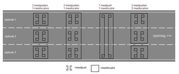
- Three separate measurement locations, each containing one detection point, with each detection point measuring one lane;
- One measurement location consisting of three detection points, with each detection point also measuring one lane;
- A single measurement location consisting of a full-lane detection point;
- Two measurement locations, with detection points distributed across the locations.
Many detection points can provide both speed and traffic flow data and, for certain data, differentiate by vehicle categories. This means an individual detection point can provide multiple data types simultaneously.
The configuration file describes the following properties for each detection point-data type-vehicle category combination:
- Data type
- Lane(s)
- Standard accuracy
- Measurement period
- Vehicle category
Each detection point must at least implement the category ‘anyVehicle,’ which aggregates results for all passing vehicles. For detection points that also implement other vehicle categories, the ‘anyVehicle’ category includes the result for all categorized and uncategorizable vehicles. The aggregation method depends on the data type. For example, traffic flow counts all vehicle passages, while for speed, it averages the speeds of all passing vehicles.
Vehicle Categories (Class lengthCharacteristic)
The Dutch DATEX II profile uses two category schemes: a three-category and a five-category scheme. Vehicles that do not meet the criteria for any category are classified as "uncategorizable" and recorded as such.
Three Categories
Detection points distinguishing three categories do not differentiate between smaller vehicle types. Also, buses and trucks are not distinguished:
| Category | Description | Length Interval |
|---|---|---|
| Cat 1 | Motorcycle, scooter, passenger car/van | <5,60 m |
| Cat 2 | Rigid truck, rigid bus | >= 5,60 en <= 12,20 m |
| Cat 3 | Articulated truck | > 12,20 en <= 25m* |
**A vehicle is "uncategorizable" if the length interval is greater than or equal to 25 meters.
Five Categories
Detection points equipped with more precise instruments can differentiate between very small and small vehicles (e.g., motorcycles and passenger cars) and between trucks and buses (based on the length difference between these two vehicle types). The five categories are:
| Category | Description | Length Interval |
|---|---|---|
| Cat 1 | Motorcycle, scooter | >= 1,85en <= 2,40 m |
| Cat 2 | Passenger car/van | > 2,40 en <= 5,60 m |
| Cat 3 | Rigid truck | > 5,60 en <= 11,50 m |
| Cat 4 | Rigid bus | > 11,50 en <= 12,20 m |
| Cat 5 | Articulated truck | > 12,20 en <= 25m* |
** A vehicle is "uncategorizable" if the length interval is greater than or equal to 25 meters.
Real-Time Data (MeasuredDataPublication)
Real-time data is delivered in the MeasuredDataPublication (MDP). This publication consists of all measurement locations listed in the MeasurementSiteTablePublication. For each measurement location, an element siteMeasurements is populated with the unique identification of the MeasurementSitethe measured information, and the timestamp of the measurement.
If available, additional information such as the number of observations used to calculate the value and the standard deviation of the current value is included. See also the description under PhysicalQuantity.
Measurement Quality
If the quality of the measurement deviates from the predefined quality in the configuration file, this should be indicated using the attribute supplierCalculatedDataQuality.
Deviating Measurement Method/Estimation
If a different calculation method is used for a measurement than specified in the configuration file, this deviation should be described using the computationalMethod attribute.
Equipment Used
If different equipment is used for a measurement than specified in the configuration file, this deviation should be described using the MeasurementEquipmentTypeUsed attribute.
No or Unreliable Data Available (Error)
If a detection point or road section provides no data, or if the data provider determines that the data is unreliable, the following attributes should be populated for each data type:
- Speed: The speed element is set to “-1.” The dataError element is set to “true.”
- Traffic flow: The vehicleFlow element is set to “0.” The dataError element is set to “true.”
- Travel time: The duration element is set to “-1.” The dataError element is set to “true.”
All other optional attributes should be omitted in this situation. See the coding specifications under PhysicalQuantity. PhysicalQuantity.
No Traffic at Detection Point
If it is determined that a detection point or road section is functioning correctly but no traffic has passed the detection point during the measurement period, the following attributes should be populated for each data type:
- Speed: The speed element is set to “0.” The numberOfInputValuesUsed element is set to “0.” The numberOfIncompleteInputs element is set to “0.”
- Traffic flow: The vehicleFlow element is set to “0.” The numberOfIncompleteInputs element is set to “0.”
- Travel time: The duration element is set to “-1.” The numberOfInputValuesUsed element is set to “0.” The numberOfIncompleteInputs element is set to “0.”
See the coding specifications underPhysicalQuantity.
Go back to the previous page